
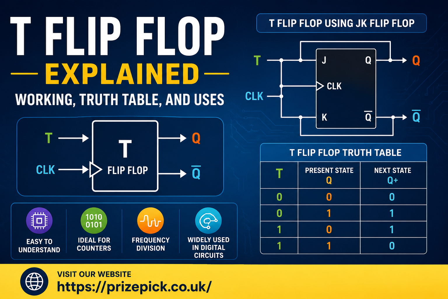
The T Flip Flop is one of the fundamental building blocks in digital electronics. Whether you’re a student learning sequential logic, an engineering enthusiast, or a professional working with digital circuits, understanding how a T Flip Flop operates is essential.
Unlike combinational logic circuits that depend only on current inputs, a T Flip Flop stores information and changes its output based on both the clock signal and its previous state. Its simple toggle behavior makes it especially useful in counters, frequency dividers, and memory systems.
What Is a T Flip Flop?
A T Flip Flop, also known as a Toggle Flip Flop, is a sequential logic circuit that changes its output state whenever its toggle input (T) is HIGH during the active clock edge.
The letter T stands for Toggle.
Unlike other flip flops that require multiple control inputs, a T Flip Flop has only one primary control input, making it simple and efficient for applications requiring repeated state changes.
Its two stable output states allow it to function as a basic one-bit memory element.
How Does a T Flip Flop Work?
The operation of a T Flip Flop depends on two signals:
- T (Toggle input)
- Clock pulse
The behavior is straightforward:
- If T = 0, the output remains unchanged.
- If T = 1, the output switches to its opposite state after the active clock edge.
For example:
| Previous Output (Q) | T | Next Output |
|---|---|---|
| 0 | 0 | 0 |
| 1 | 0 | 1 |
| 0 | 1 | 1 |
| 1 | 1 | 0 |
This toggling action is what gives the flip flop its name.
T Flip Flop Truth Table
The truth table summarizes the behavior of the circuit.
| Clock Edge | T | Present State (Q) | Next State (Q+) |
|---|---|---|---|
| Rising Edge | 0 | 0 | 0 |
| Rising Edge | 0 | 1 | 1 |
| Rising Edge | 1 | 0 | 1 |
| Rising Edge | 1 | 1 | 0 |
A simpler interpretation is:
| T | Output Action |
|---|---|
| 0 | No Change |
| 1 | Toggle |
This simple logic makes the T Flip Flop easy to analyze and implement.
Characteristic Equation
The characteristic equation describes the relationship between the present state and the next state.
Q(next) = T XOR Q
This equation means:
- When T equals 0, the output stays the same.
- When T equals 1, the output becomes the opposite of its previous value.
The XOR operation perfectly represents the toggle behavior.
Symbol of a T Flip Flop
A typical T Flip Flop symbol includes:
- One T input
- One clock input
- Q output
- Q̅ (complement output)
The clock input is usually represented by a small triangle indicating edge-triggered operation.
Circuit Implementation
Although dedicated T Flip Flops exist, many digital circuits create one from a JK Flip Flop.
Using a JK Flip Flop
The simplest implementation connects:
- J = T
- K = T
This configuration produces:
- J = K = 0 → Hold
- J = K = 1 → Toggle
Because both inputs receive the same signal, the JK Flip Flop behaves exactly like a T Flip Flop.
Using a D Flip Flop
A T Flip Flop can also be implemented using a D Flip Flop with an XOR gate.
The equation becomes:
D = T XOR Q
This arrangement allows the D Flip Flop to perform toggle operations.
Timing Diagram Explained
The output changes only on the active edge of the clock.
For example:
- Clock pulse arrives
- T = 0
- Output remains unchanged
Next clock pulse:
- T = 1
- Output toggles
Following clock pulse:
- T = 1
- Output toggles again
Because changes occur only during clock transitions, timing remains synchronized throughout the digital system.
Applications of a T Flip Flop
The T Flip Flop appears in numerous digital systems.
1. Binary Counters
Each clock pulse changes the output state.
Connecting multiple T Flip Flops creates:
- Ripple counters
- Synchronous counters
- Asynchronous counters
2. Frequency Division
Every clock pulse toggles the output.
As a result:
Output frequency = Input frequency ÷ 2
Connecting several T Flip Flops divides the frequency further.
3. Digital Clocks
Many digital clocks rely on T Flip Flops to generate timing signals and count seconds, minutes, and hours accurately.
4. State Machines
Finite state machines often use T Flip Flops to manage transitions between states.
5. Memory Circuits
Although not commonly used as standalone memory, they contribute to larger sequential storage systems.
6. Control Systems
Industrial controllers frequently use T Flip Flops to synchronize events and sequence operations.
Advantages of a T Flip Flop
The T Flip Flop offers several benefits.
- Simple design
- Only one input signal
- Easy to understand
- Reliable toggle operation
- Ideal for counters
- Excellent for clock division
- Low hardware complexity
Its straightforward behavior reduces design complexity in many digital circuits.
Disadvantages of a T Flip Flop
Despite its usefulness, there are some limitations.
- Cannot directly store arbitrary data like a D Flip Flop
- Less versatile than JK Flip Flops
- Requires clock synchronization
- Propagation delay increases in ripple counter configurations
Understanding these limitations helps designers choose the right flip flop for specific applications.
T Flip Flop vs JK Flip Flop
| Feature | T Flip Flop | JK Flip Flop |
|---|---|---|
| Inputs | One | Two |
| Primary Function | Toggle | Set, Reset, Hold, Toggle |
| Complexity | Simple | More Complex |
| Counter Design | Excellent | Excellent |
| Hardware Cost | Lower | Higher |
| Flexibility | Limited | Greater |
The JK Flip Flop is more flexible, while the T Flip Flop is simpler and more efficient for repetitive toggling operations.
T Flip Flop vs D Flip Flop
| Feature | T Flip Flop | D Flip Flop |
|---|---|---|
| Input | Toggle | Data |
| Main Purpose | Toggle State | Store Data |
| Common Applications | Counters | Registers |
| Circuit Complexity | Low | Moderate |
| Output Change | Toggle | Follow Input |
Each serves a different purpose depending on the digital system’s requirements.
Practical Example
Suppose a T Flip Flop starts with:
- Q = 0
- T remains HIGH
Clock pulses produce:
| Clock Pulse | Output |
|---|---|
| Initial | 0 |
| First | 1 |
| Second | 0 |
| Third | 1 |
| Fourth | 0 |
The output continuously alternates between HIGH and LOW.
This behavior is why T Flip Flops are widely used for frequency division.
Common Mistakes When Learning T Flip Flops
Students often make these mistakes:
- Ignoring the clock edge
- Confusing T Flip Flop with JK Flip Flops
- Forgetting that T = 0 keeps the previous state
- Assuming the output changes continuously instead of only at clock transitions
Keeping these points in mind makes understanding sequential logic much easier.
Why T Flip Flops Matter in Digital Electronics
Modern electronic devices depend on precise timing and predictable state changes.
T Flip Flops contribute to:
- Computer processors
- Embedded systems
- Communication equipment
- Digital measuring instruments
- Consumer electronics
- Industrial automation
- Microcontroller-based projects
Although they represent a simple circuit element, they form the foundation of much larger digital systems.
Frequently Asked Questions
1. What does the “T” in T Flip Flop stand for?
The “T” stands for Toggle, indicating that the output changes to the opposite state when the T input is HIGH during the active clock edge.
2. What is the main purpose of a T Flip Flop?
Its primary purpose is to toggle the output state, making it ideal for counters, clock division, and sequential logic circuits.
3. Can a T Flip Flop be built from a JK Flip Flop?
Yes. By connecting the J and K inputs together, a JK Flip Flop behaves exactly like a T Flip Flop.
4. Why is a T Flip Flop used in counters?
Each clock pulse toggles the output, naturally creating binary counting sequences when multiple T Flip Flops are connected.
5. What happens when T equals 0?
When T is LOW (0), the output retains its previous state regardless of the clock pulse.
6. What happens when T equals 1?
When T is HIGH (1), the output changes to the opposite state at the active clock edge.
7. Is a T Flip Flop edge-triggered?
Most modern T Flip Flops are edge-triggered, meaning they respond only on the rising or falling edge of the clock signal, depending on the design.
Conclusion
The T Flip Flop is one of the simplest yet most valuable components in digital electronics. Its unique ability to toggle between states with each clock pulse makes it indispensable for binary counters, frequency dividers, state machines, and timing circuits. By understanding its working principle, truth table, characteristic equation, and practical applications, students and engineers gain a strong foundation in sequential logic design. Whether you’re studying digital systems or designing electronic circuits, mastering the T Flip Flop is an important step toward understanding how modern digital devices store, process, and synchronize information efficiently.